GROUP 4 PROJECT- 2009Connor Scheu and Wouter Zwart April 2, 2009
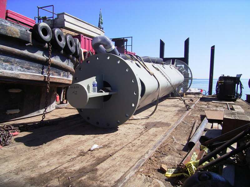
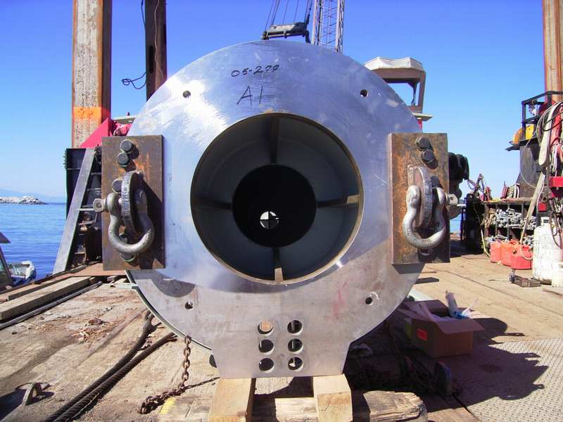
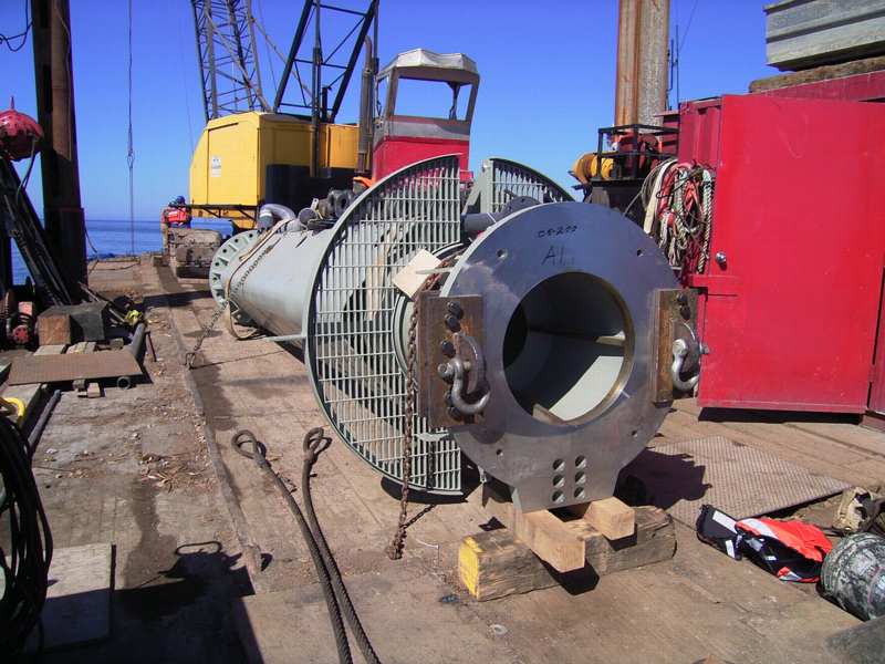
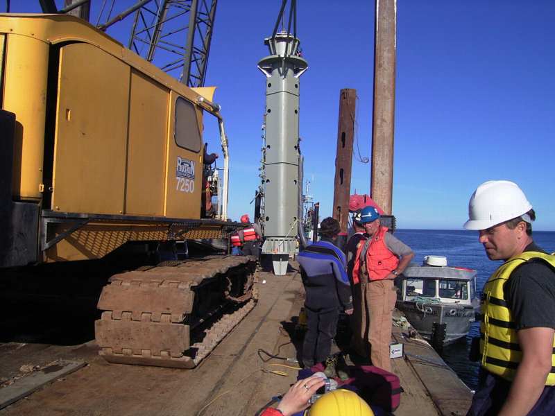
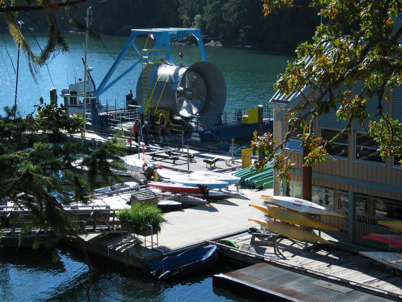
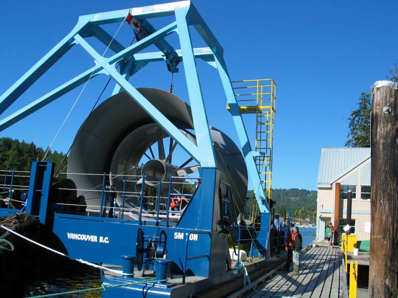
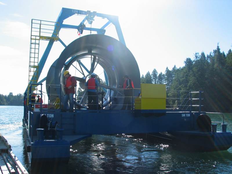
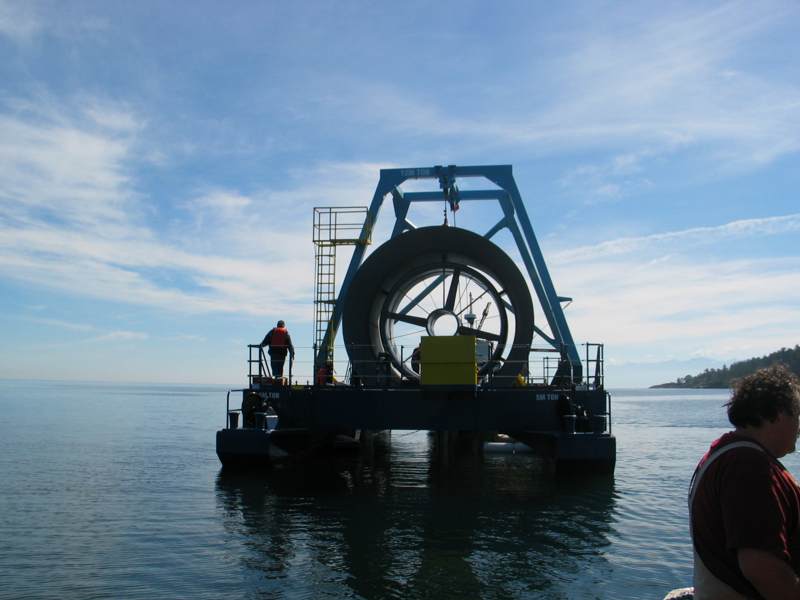
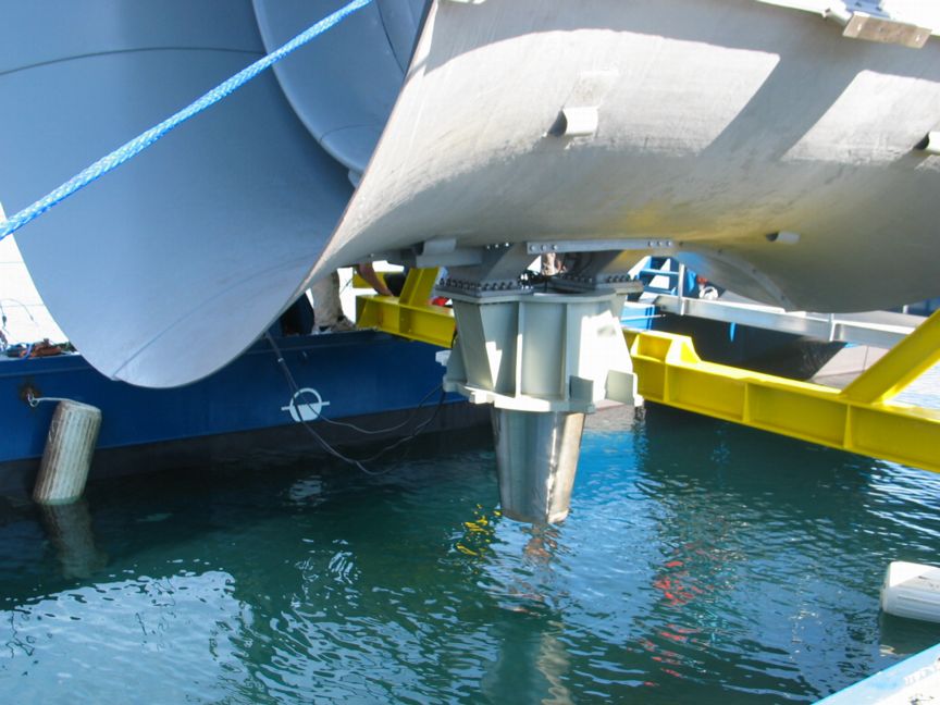
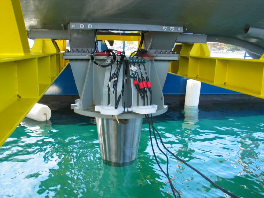
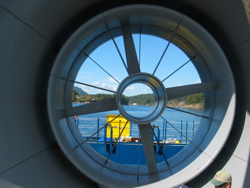
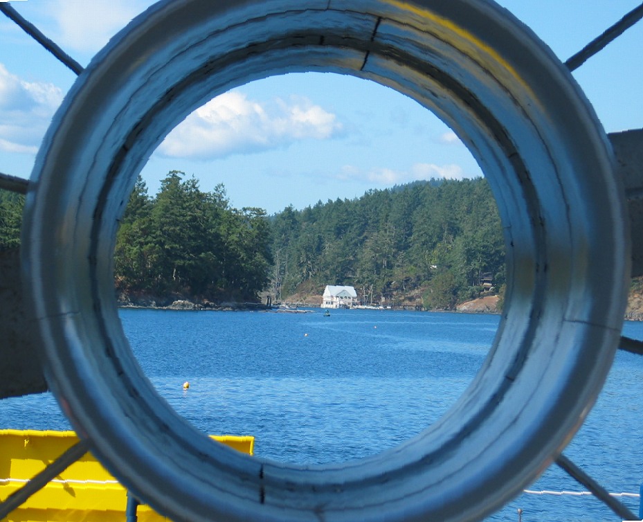
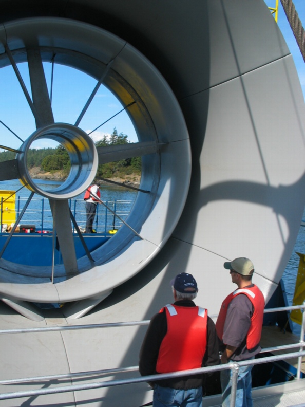
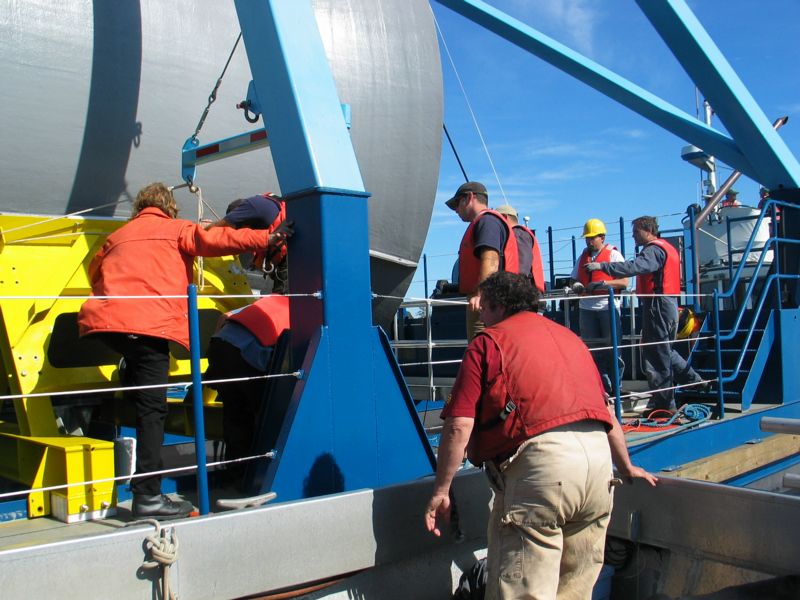
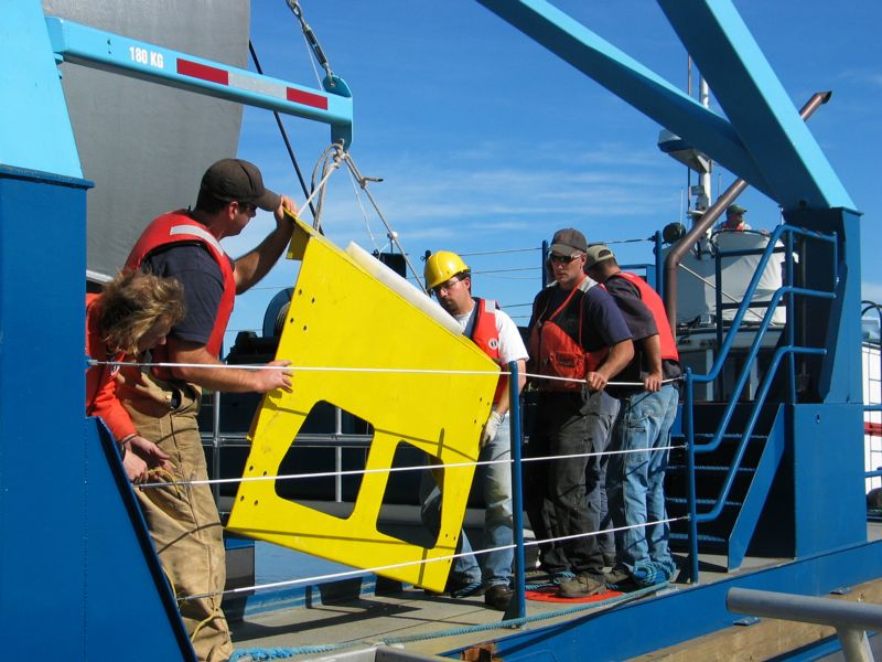
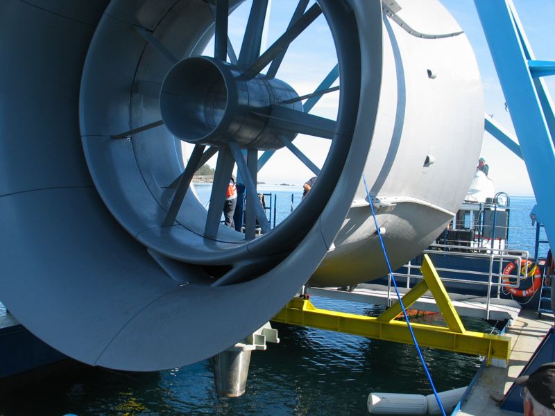
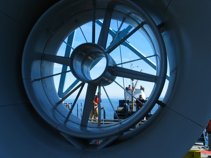
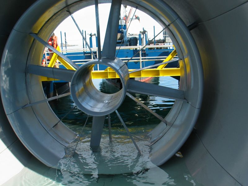
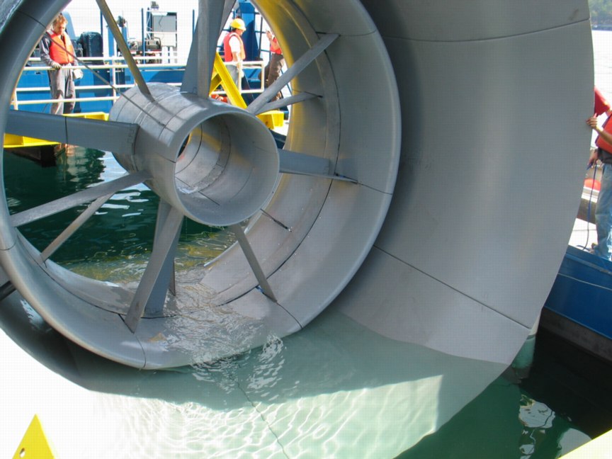
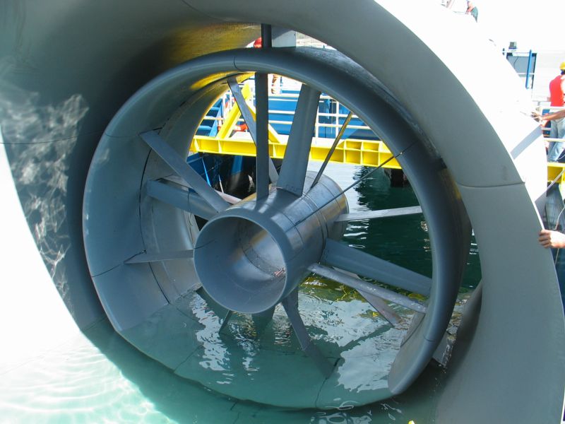
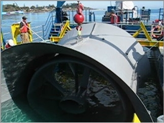
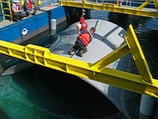
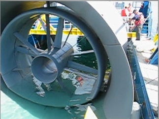
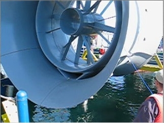
Race Rocks Tidal Turbine Generator
Background:
Connor communicated with Russ Stothers of Clean Current for his project;
“Here is a simple synopsis of the project I will be doing this week. It is called a group four project (which pertains to the experimental science department here at the college), and the theme for everyones project is resource allocation/sustainability. Every student has to decide upon a project in which they will research something in this area. This usually involves the identification of a question, and then variables, presented in a lab format and accompanied by a presentation, but not overly formal.
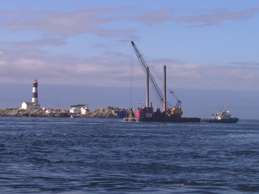
For my project I really wanted to do something close to home, so I naturally thought of the tidal generator. I thought it would be so great if I could use this project to become more familiar with the project, and learn more about the field in general. It was for this reason that I wanted to contact you.
So basically what I would require for my project is some simple data, on the energy output of the generator, hopefully in relation to the tidal currents. From this I hope to create a simple relationship, proportional or not, which will help me identify the output and efficiency as current varies. This would satisfy the lab component of my project. The next component I would pursue would be the application of this knowledge. Simply from the results of the data and correlation I hope to receive, I would apply some simple reasoning to determine how effective or feasible such technology would be in other circumstances. That is, different magnitudes, in size and tidal extremes. An example of this would be; if the generator receives pique efficiency at the lowest speeds, then the technology would be more widely applicable to more general locations in the world, as opposed to selective areas of high tidal motion. Or if the energy benefits of higher speeds outweigh the selectivity of the projects.
This may be a rather ambitious goal, however this is a less formal project than others at the college (the extended essay is a full research paper) and as such it is OK to have lofty goals and then only achieve some of them in the allotted time. However I am sure that with your help I will be fully capable of receiving satisfactory results.
So I guess what I am asking of you would be the data I have previously outlined, in addition to the answering of some basic questions on the running of the turbine (included below this message).
This help would be most appreciated, I think it would be highly beneficial for the students of the college to have a little more information on the nature of this project. As it is so unique in design, important to global issues, and close to home. This is what my project will allow, as I will be presenting my findings to the student body towards the end of the week. I am very grateful for your generosity and aid
thank you again
Connor Scheu
Here are some of the questions which I have identified as what I think I need to know. But please feel free to include any relevant knowledge that you think would help. I am still quite unfamiliar with the project, and as such my questions may be a little vague. Also feel free to not answer any questions if they breach any kind of protocol or patent information.
1. Is this in fact just a simple turbine generator (similar to those in other hydro operations) placed in the presence of a fast moving current, or does it have certain defining characteristics.
No, it is significantly different from other hydro turbines. The requirement to extract power from a bi-directional flow means that the design of the turbine blade is very different. All standard hydro applications have blades that are designed to accept flow in one direction. Another major difference is that our machine is direct drive so that the speed of the generator is very slow compared to traditional applications which use a gearbox and a high speed generator.
2. What is the magnitude of energy created, when compared with other forms of green energy, is it relatively efficient etc.
The magnitude of the energy with respect to efficiency is very similar to wind in that the same basic laws of physics apply. The big difference/benefit is that the energy produced by tides is completely predictable whereas wind energy is statistically predictable over long periods of time but impossible to predict from one minute to the next.
I wouldn’t try to compare tidal energy to solar, biomass or other renewables. Each form of renewable energy is site specific.
3. Is this technology quite expensive to install, does it require very specific natural circumstances to operate effectively.
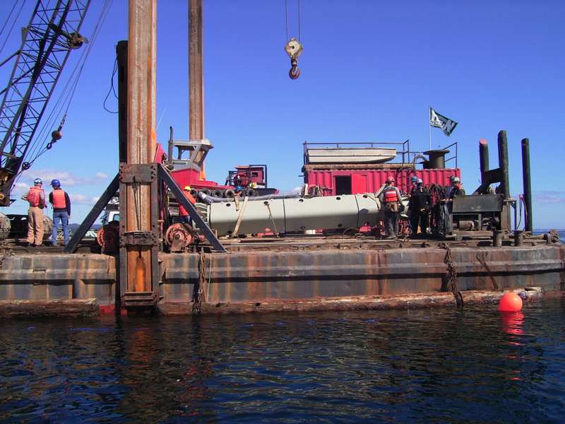
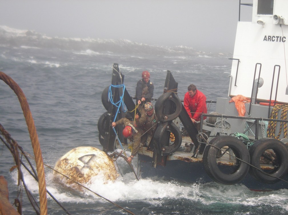
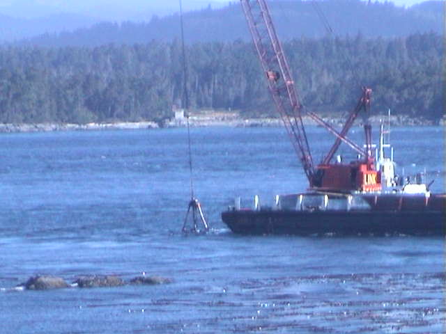
At the present time, yes. One of the biggest challenges facing the industry is to develop a system to cost effectively deploy, maintain and retrieve these devices. As you can understand from your experience at Race Rocks, the weather combined with the high tidal currents makes any deployment activity very difficult. The technology is best suited to sites that have peak tidal velocities between 2.5 m/s and 5.0 m/s. At current speeds less than 2 m/s there is very little energy in the flow and at speed greater than 5 m/s cavitation becomes a significant issue.
4. Is it true that this is one of only four projects like this in the world, and if so, what are the natures of the others. That is how do they differ, or are similar. Also, what immediate repercussions could this technology have on the world if proven to be effective.
Clean Current’s principal competitors are based in Europe. There are many competitors but the ones Clean Current considers threats are:
Marine Current Turbines is the most advanced with the deployment of a 1.2MW unit at Strangford Lough in 2008. Clean Current believes the challenges of this system compared to the Clean Current technology are as follows:
This unit has a high capital cost due to the complexity and large number of moving parts (gearbox, variable pitch blades, mechanism to raise and lower rotor).
The structure is surface piercing and therefore a navigational hazard to recreational and commercial traffic.
The exposed rotating blades pose a threat to fish, marine life and divers.
The above water structure must be designed to survive extreme weather such as hurricanes and tsunamis.
The turbine is sensitive to flow directional changes as it does not have an upstream augmenter to redirect the flow.
The system is complex and not applicable in deep water applications which comprise the majority of the world’s resources.
Open Hydro is a well financed company based in Ireland. They have deployed a 6m prototype of their technology at the EMEC testing centre. They are also planning to deploy a second unit in the Bay of Fundy in the summer of 2009. Clean Current believes the challenges of this system compared to the Clean Current technology are as follows:
The fixed pitch blades are similar to flat plates and therefore have a poor efficiency. Clean Current’s blades are also fixed pitch but use a highly efficient hydrodynamic shape.
The overall efficiency of this unit is much lower than Clean Current’s turbine due to the lack of a power augmenting outer duct.
The lack of a central support makes the turbine more susceptible to vibration caused by the turbulent tidal flow The turbine cannot compensate effectively for flow directional changes as it does not have an upstream augmenter to redirect the flow.
The design information currently available does not indicate the use of a maintenance module potentially resulting in significant downtime.
5. Is this technology a great improvement on the other forms of tidal generation, which typically involve the use of dikes and grand structures.
The traditional barrage types of technology have large environmental impacts. The type of tidal generation that we are promoting does not have the same effect on the ecosystem; however, it is important to note that barrage types of technology can extract greater amounts of energy as all of the flow is forced through the turbine.
6. What are some of the typical pitfalls in this kind of project, some main difficulties either with engineering, or other aspects.
Some of the main challenges from the engineering side are as follows:
Deployment in fast moving waters (as discussed above)
Operation of bearings in a submerged environment
Operation of an electrical machine in a submerged environment.
Transmission of the power to shore
Achieving maintenance free operation for 5+ years.
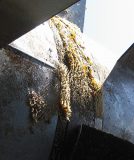
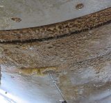
Prevent bio-fouling
Some of the non-technical issues include:
Regulatory approvals from organizations such as DFO on the perceived impact on marine life
Negotiations with existing users of area (fisherman, tug operators, commercial vessels) to accommodate the installation of a tidal farm
I think these are sufficient to give me a basic comprehension of what this project is about. I will also make an effort to research what I can on my own, I just thought I would make use of you as a resource if possible.
thanks again
Connor Scheu
Questions:
1. I am still unsure as to the nature of the “upstream augmenter.” I know that it allows for the turbine to compensate for flow direction changes, I am just not sure how it does this, or what it is really.
The curved shape of the augmentor redirects the flow so that the water is directly aligned with the turbine rotor. Without an augmentor, the flow would intersect the rotor at an acute angle which would result in reduced power output. You can also think of the augmentor as functioning similar to a sail on a sailboat. When the sail is trimmed properly, the wind follows the shape of the sail. We have designed the augmentor so that for flow deviations, the water follows the surface of the augmentor.
2. The transmission of power to shore, is done by means of an underwater cable? Is this the only means by which this can be done, and is this a very difficult procedure?
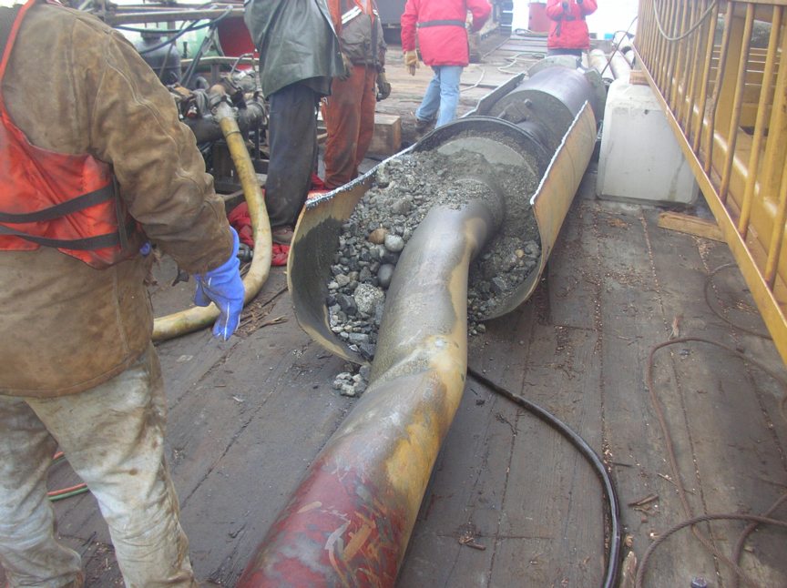
The only way to bring significant power ashore is through the use of a subsea cable. The challenges of this technology are ensuring the cable is adequately protected on the seabed. Due to the high current environment, the cable is very susceptible to damage through abrasion on the rocky seabed. Another challenge is electrical connectors. The majority of the connectors available in industry are not designed for both high power and long life. A specific design for tidal generators is required.
3. You mentioned the biological impact, I understand how this turbine is significantly better than the barrage designs, and even than the open bladed design of the other company. I presume that it is fairly safe (simply by looking at the design) because large animals will avoid the turbine, and smaller fish may pass through without harm. Is this somewhere in the right ballpark. Are there any other concerns for the local wildlife?
You thoughts are inline with ours. I think your best source for an opinion here is probably Chris.
4. It seems to me as if you guys are the best outfit going, would you consider yourselves the world leaders in this technology, or at least one of the most promising companies.
Thanks for the comments! Yes, we believe that we are one of the leading technologies. Having said this; however, there is still significant work to be performed to make this product commercial.
5. You mentioned that the majority of the world’s resources are located in deep water, what kind of limitations does your technology have on depth? Are there a multitude of possible locations for this technology around the world, what would be some of the ideal circumstances?
When we refer to deep water, we are referring to 40-65m of water. Our technology is well suited to these depths. As you go deeper, the greatest challenge will be installation. The paragraph below is an excerpt from our assessment of the market.
Global demand for electric power is expected to increase from 14.8 trillion kilowatt hours in 2003 to 30.1 trillion kilowatt hours by 2030, according to the Energy Information Administration. To meet this demand, the International Energy Agency estimates that investments in new generating capacity will exceed $4 trillion in the period from 2003 to 2030, of which $1.6 trillion will be for renewable energy generation equipment.
A variety of factors are contributing to the development of renewable energy systems that capture energy from replenishable natural resources, such as ocean currents and waves, flowing water, wind and sunlight and convert it into electricity. These factors include the rising cost of fossil fuels, dependence on energy from foreign sources, environmental concerns, government incentives and infrastructure constraints.
Tidal energy is positioned favourably to capitalize on the growing demand for renewable energy. It is expected that tidal energy generation costs for large sites will be competitive with other renewable energy sources. In addition to having the potential to be a very large source of competitive renewable energy, tidal energy is a very predictable source of energy, is not affected by climate change and has a minimal environmental footprint.
Clean Current expects early adoption of tidal power generation will be driven by those countries and regions that are looking to satisfy government or regulatory renewable energy mandates and that have potential tidal energy resources situated near populations with high electricity demand and relatively high power prices. A number of communities and utilities in the United Kingdom, North America and Asia are currently pursuing tidal energy feasibility studies, and are expected to be some of the first regions to pursue tidal farms when a proven commercial technology becomes available.
Recent government sponsored initiatives have included tidal resource assessments from leading engineering consulting firms, Black & Veatch Corporation (“Black & Veatch”) (United Kingdom) and Triton Consultants Ltd. (“Triton Consultants”)(Canada), respectively. Black & Veatch estimated the world’s “Technically Extractable Resource” to be 155 TWh per annum, including 18 TWh At an average capacity factor of 26%, this?per annum in the United Kingdom. translates to installed capacity of approximately 67,400 MW for the world and 7,800 MW for the United Kingdom.
In Canada, Triton Consultants assessed the tidal energy potential at approximately 42,000 MW. Approximately 7,000 MW of this potential resource is located in accessible regions on the east and west coasts of Canada.? Clean Current estimates that approximately 15% to 20% of the power in the accessible regions is currently extractable, resulting in 9.2 to 12.3 TWh per annum of electrical energy. At an average capacity factor of 26%, this translates to installed capacity of approximately 4,000 to 5,500 MW for Canada.
1. Source: Phase II, UK tidal Stream Energy Resource Assessment; Black & Veatch
2. Source: Canada Ocean Energy Atlas (Phase 1) Potential Tidal Current Energy Resources Analysis Background; Triton Consultants
Again, I am very grateful for all of your help, I read on the company site that one of the mandates of this project was to aid in the education of the students of Pearson College. I think this is very thoughtful, and says something about the quality of your company, and of course, its employees.
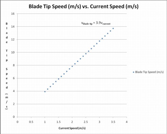
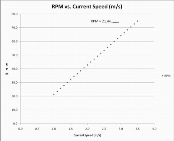
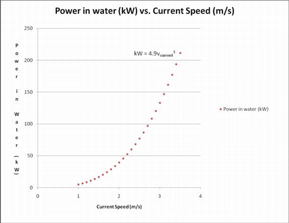
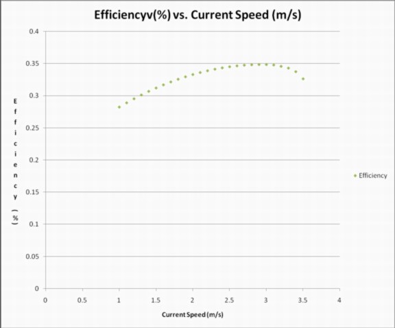
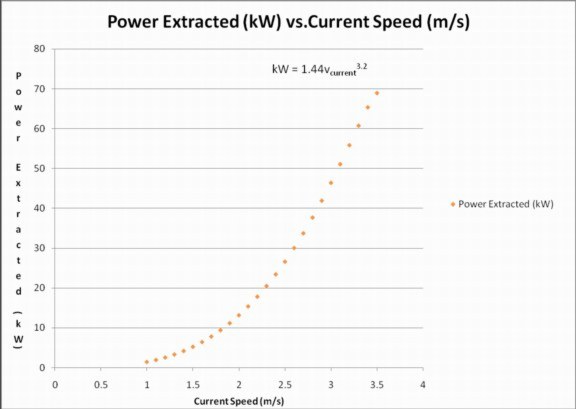
Purpose: To determine the correlation between the rates of current flow through the channel and the power produced by the generator, and then apply said correlation to real world applications.
Procedure: Experimentation performed by Clean Current and its employees
Data:
| Diameter of Turbine | m | 3.5 |
| Frontal Area | m2 | 9.62 |
| Density of Seawater | Kg/m3 | 1024 |
| Current Speed | Blade Tip Speed | RPM | Power in water | Efficiency | Power Extracted |
| (m/s) | (m/s) | (kW) | (%) | (kW) | |
| 1.0 | 3.9 | 21.4 | 4.9 | 28.2% | 1.4 |
| 1.1 | 4.3 | 23.5 | 6.6 | 28.9% | 1.9 |
| 1.2 | 4.7 | 25.7 | 8.5 | 29.5% | 2.5 |
| 1.3 | 5.1 | 27.8 | 10.8 | 30.1% | 3.3 |
| 1.4 | 5.5 | 30.0 | 13.5 | 30.7% | 4.1 |
| 1.5 | 5.9 | 32.1 | 16.6 | 31.2% | 5.2 |
| 1.6 | 6.3 | 34.2 | 20.2 | 31.7% | 6.4 |
| 1.7 | 6.7 | 36.4 | 24.2 | 32.2% | 7.8 |
| 1.8 | 7.1 | 38.5 | 28.7 | 32.6% | 9.4 |
| 1.9 | 7.5 | 40.7 | 33.8 | 33.0% | 11.1 |
| 2.0 | 7.8 | 42.8 | 39.4 | 33.3% | 13.1 |
| 2.1 | 8.2 | 44.9 | 45.6 | 33.6% | 15.3 |
| 2.2 | 8.6 | 47.1 | 52.5 | 33.9% | 17.8 |
| 2.3 | 9.0 | 49.2 | 59.9 | 34.2% | 20.5 |
| 2.4 | 9.4 | 51.4 | 68.1 | 34.4% | 23.4 |
| 2.5 | 9.8 | 53.5 | 77.0 | 34.5% | 26.6 |
| 2.6 | 10.2 | 55.6 | 86.6 | 34.7% | 30.0 |
| 2.7 | 10.6 | 57.8 | 97.0 | 34.8% | 33.7 |
| 2.8 | 11.0 | 59.9 | 108.1 | 34.8% | 37.7 |
| 2.9 | 11.4 | 62.1 | 120.1 | 34.9% | 41.9 |
| 3.0 | 11.8 | 64.2 | 133.0 | 34.9% | 46.4 |
| 3.1 | 12.2 | 66.3 | 146.8 | 34.8% | 51.1 |
| 3.2 | 12.5 | 68.5 | 161.4 | 34.6% | 55.8 |
| 3.3 | 12.9 | 70.6 | 177.0 | 34.3% | 60.8 |
| 3.4 | 13.3 | 72.8 | 193.6 | 33.8% | 65.4 |
| 3.5 | 13.7 | 74.9 | 211.2 | 32.6% | 68.9 |

